How to configure people counting via VIGI VMS
Contents
The preliminary steps to implement People Counting
Configuring people counting via VIGI VMS
Objective
This article introduces how to configure the People Counting feature on VIGI VMS. It covers application scenarios, a configuration guide, usage tips, and a list of supported devices (NVR and IPC).
Introduction
The People Counting feature is primarily applied in commercial retail stores and supermarkets. Analyzing the data of pass-by, walk-ins, and walk-outs generates detailed people counting reports. These people counting reports empower businesses to:
- Optimize store layouts and enhance conversion rates by identifying high-traffic zones.
- Optimize operational strategies, including staff scheduling and inventory management, by adjusting resource allocation with peak-hour trends.
- Conduct sales forecasting and adjust marketing tactics based on People Counting data, enabling data-driven decision-making for market strategy optimization.
The application scenarios are complex and diverse. To improve the accuracy of People Counting, it recognizes people by detecting their head features.
Requirements
Preparation before Configuration
Before you start using People Counting, make sure your devices support it. Devices Supported by People Counting: https://www.vigi.com/vigi-people-counting/product-list/.
Requirements for Using VIGI Local VMS
- VIGI Local VMS software
- A VIGI Network Video Recorder (NVR)
- A compatible VIGI IP camera
- Ensure the IP camera is successfully added to the NVR and assigned to an active channel
Requirements for Using VIGI Cloud Service
- A VIGI Cloud Service account
- A compatible VIGI IP camera
Note: The VIGI Cloud Service does not currently support People Counting. This feature will be available in a future update.
Configuration
The preliminary steps to implement People Counting
- VIGI VMS + VIGI IPC: Enable the People Counting functionality on the NVR.
Step 1. Go to Devices, and click on edit for the NVR to be configured with “People Counting” function.
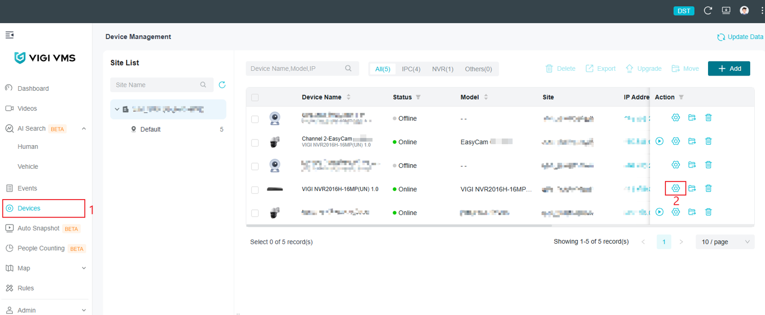
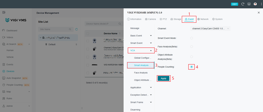
Step 2. Go to Event, VCA, Smart Analysis Configuration. Select People Counting and Click Apply. Device will reboot. Wait about 5 minutes and refresh the page to check the settings.
Configuring people counting via VIGI VMS
The following section provides the configuration steps for setting up People Counting using VIGI VMS.
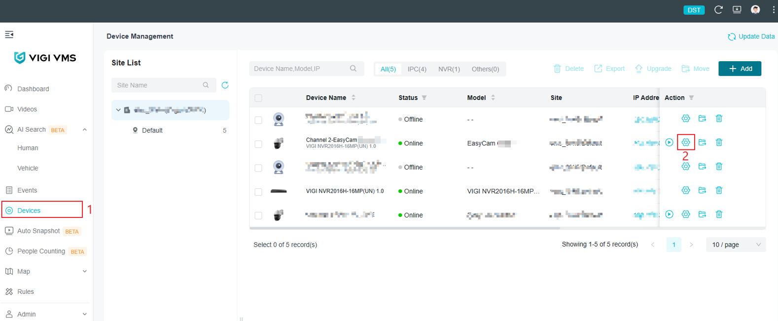
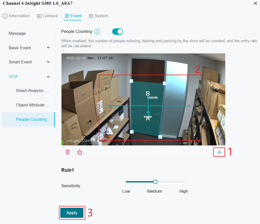
Step 1. Go to Devices, click on edit for the device to be configured with People Counting function.
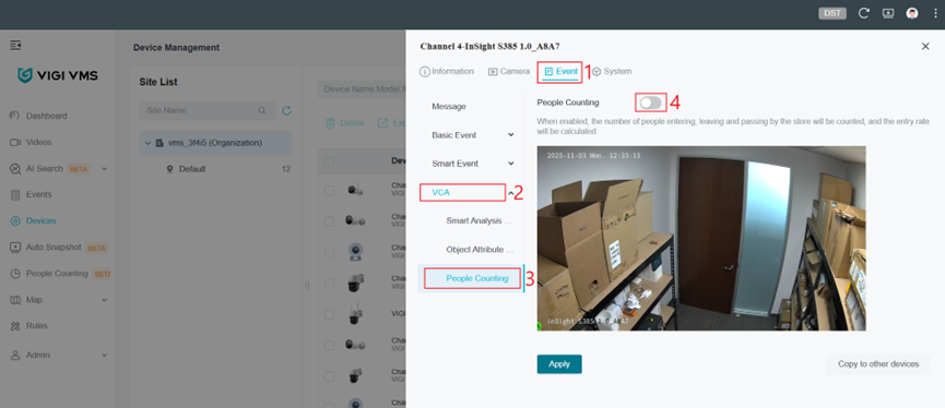
Step 2. Go to Event, VCA, Click on People Counting.
Step 3. Click on ‘+’ to create the People Counting areas and set the entry and exit rules.
-
- A maximum of 3 people counting areas can be created.
- People counting areas cannot overlap.
- Please leave some space between the edge of the People Counting area and the edge of the IPC monitoring frame.
- The detection areas and rules should be adjusted based on the specific scenario.
Rule Description
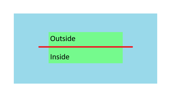
Assume the blue area is the IPC’s monitoring view, the green area is the People Counting area, and the red line splits the green area into an "Inside" and "Outside" area. The People Counting rule requires a trajectory of the human head to pass through the green area—meaning the human head must first appear in the blue area, then enter the green area, and finally exit the green area back into the blue area.
The People Counting rule determines whether the movement is a Walk-in, Walk-out, or Pass-by based on the position of the entry and exit points within the green area (i.e., the boundary points of the green area). Below is a detailed explanation of what defines a Walk-in, Walk-out, or Pass-by.
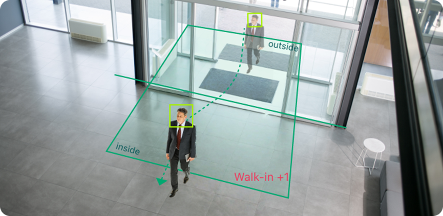
- Walk-in
In the diagram below, the dotted green line represents the trajectory of a person’s head, traveling from the top to the bottom within the green area. The human head moves from the outside area into the green area and then out the inside area, creating two intersection points: A and B.
- Point A, where the trajectory enters the green area, is located in the Outside region.
- Point B, where the trajectory exits the green area, is located in the Inside region.
As a result, the person is recognized as entering from the Outside and leaving from the Inside, which is counted as one visitor entry (Walk-in +1).
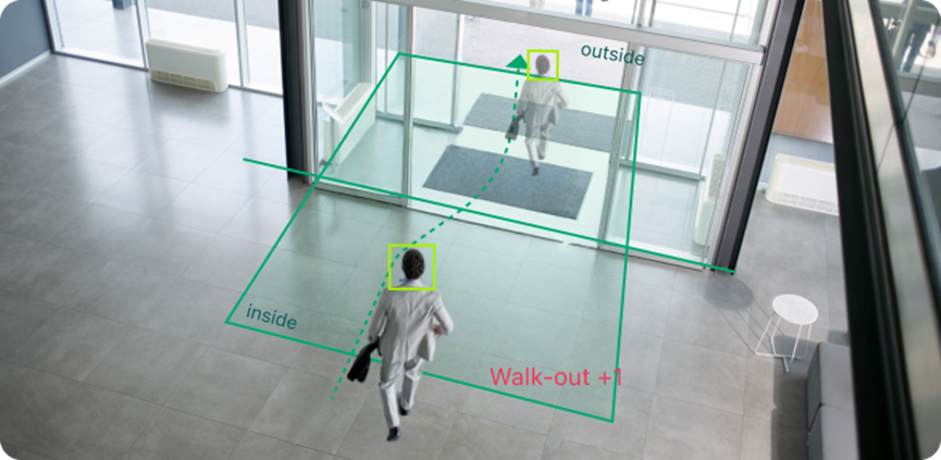
- Walk-out
In the diagram below, the dotted green line represents the trajectory of a person’s head, traveling from the bottom to the top within the green area.
- Point A, where the trajectory enters the green area, is located in the Inside region.
- Point B, where the trajectory exits the green area, is located in the outside region.
As a result, the person is recognized as entering from the Inside and leaving from the Outside, which is counted as one visitor exit (Walk-out +1).
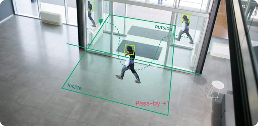
- Pass-by
In the diagram below, the green dotted line represents the trajectory of a person’s head, traveling from the right to the left within the green area.
- Point A, where the trajectory enters the green area, is in the Outside region.
- Point B, where the trajectory exits the green area, is in the Outside region.
As a result, the movement is recognized as entering from Outside and leaving from Outside, which is counted as one pass-by (Pass-by +1).
(Although the human head crosses the green line and enters the Inside region, it remains within the green area and wanders without exiting from the Inside boundary. Instead, it exits from the Outside boundary. Therefore, it is not recognized as a visitor entry but as a pass-through.)
Notes:
The People Counting rule requires that the trajectory pass through the green area rather than simply remaining within it. It's essential to leave some space between the green area and the edges of the uncolored area so the system can recognize a complete travel.
The system does not care what the target does within the green or uncolored areas. It only considers the entry and exit points of the green area and determines whether those points are located Inside or Outside the green area.
- Enter from Outside, exit from Inside → Counted as Walk-in
- Enter from Inside, exit from Outside → Counted as Walk-out
- Enter from Outside, exit from Outside → Counted as Pass-by
- Enter from Inside, exit from Inside → Invalid data
- Appears suddenly in the green area, entry point unknown; regardless of exit point → Invalid data
- Enters green area but disappears suddenly, exit point unknown → Invalid data
- Moves only within the uncolored area without entering the green area → Invalid data
Step 3. Select the periods for when People Counting will be active, then click Apply.
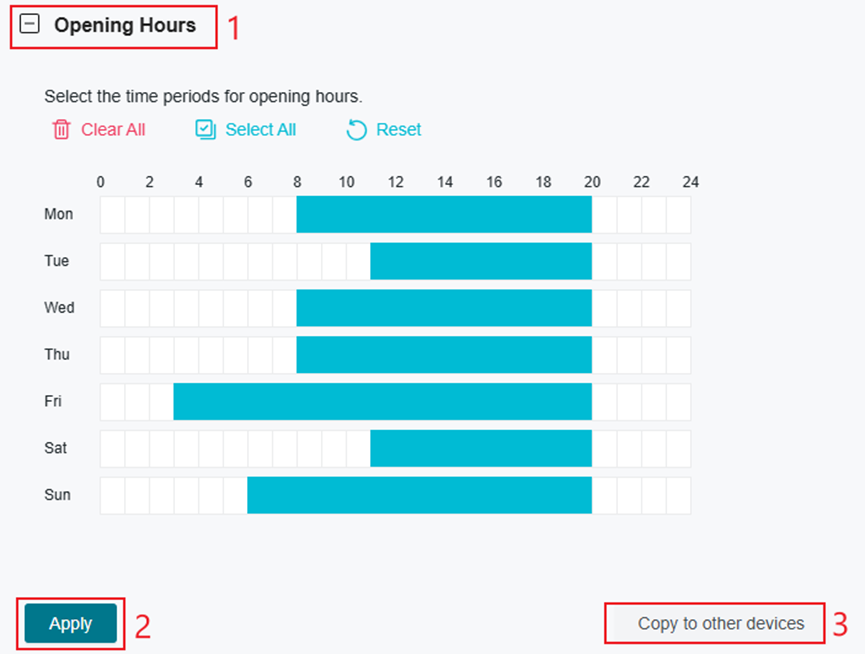
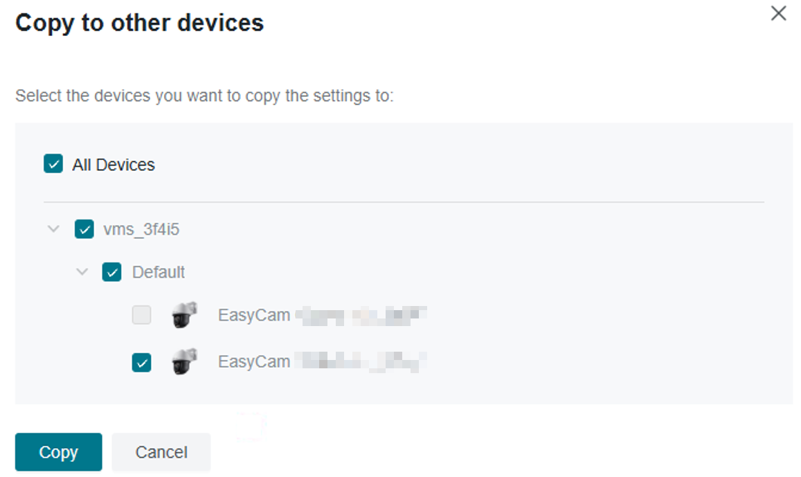
Step 4. (Optional) To apply these settings to other devices, click Copy to other devices. Select the devices to which you want to copy the settings.
Verification
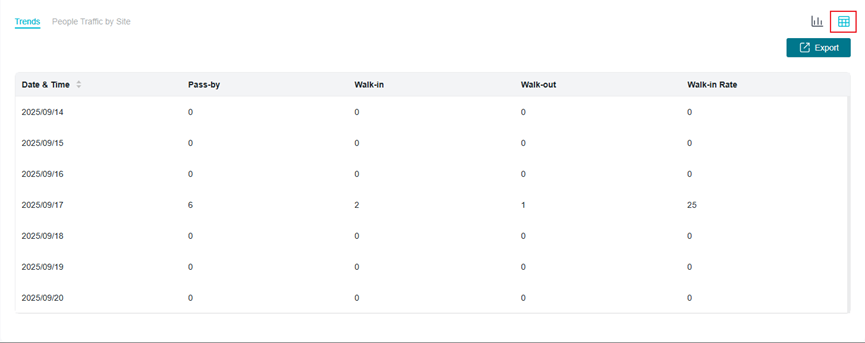
Once People Counting has been configured, select People Counting on the left menu to view statistics and metrics. An explanation of the available options are described below.
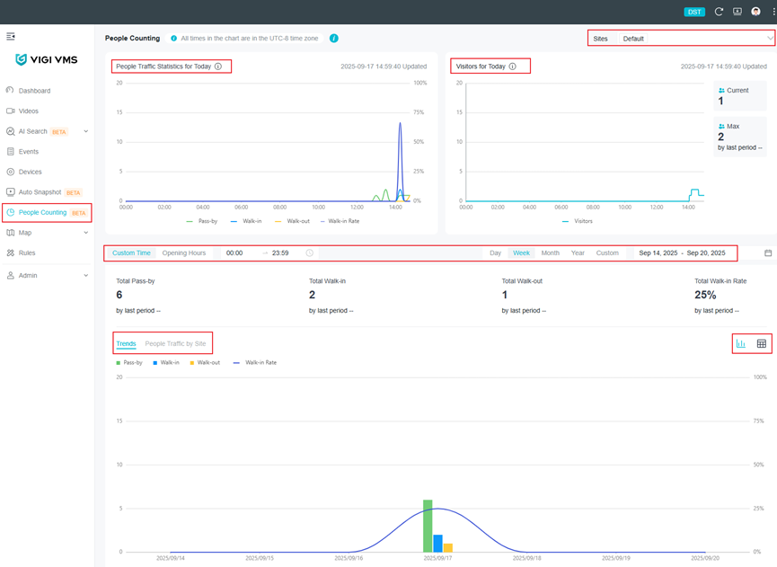
- Select sites: Located at the top right of the page. The data between different sites is isolated, and real-time calculations are performed. (The calculations follow relevant statistical algorithms rather than simple aggregation.)
- People Traffic Statistics for Today: This displays statistical data from midnight in the organization's time zone to the current time, with one data point every 15 minutes (calculating data for the completed 15-minute intervals, while incomplete intervals are not displayed). The data includes pass-by, walk-in, walk-out, and walk-in rates and refreshes automatically every minute.
- Visitors for Today: This module displays real-time visitors. In addition to the visitors for today trend chart, it includes the current number of visitors, the maximum number of visitors for today, and the growth rate of today's peak walk-in visitors compared to yesterday. The data is automatically refreshed every minute.
- Time: The time selection includes a custom time mode, where you can choose the start and end times for each day, with a minimum interval of half an hour. You can also select the opening hours mode, which will calculate data based on the opening hours configured on each device. The date selection includes multiple modes: day, week, month, year, and custom.
- Total statistics: This includes pass-by, walk-in, walk-out, walk-in rate, and corresponding period-over-period growth data.
- Trends: This chart displays based on the chosen time selection mode, including the data of pass-by, walk-in, walk-out, and walk-in rates. You can switch the chart to the People Traffic by site mode.
- Table Mode and Data Export: In addition to the chart display, you can switch to table mode in the top right corner of the chart. In table mode, you can also export the data.
General usage tips
Camera Installation Guidelines
To ensure optimal performance and accurate people counting, please follow the recommended installation guidelines below:
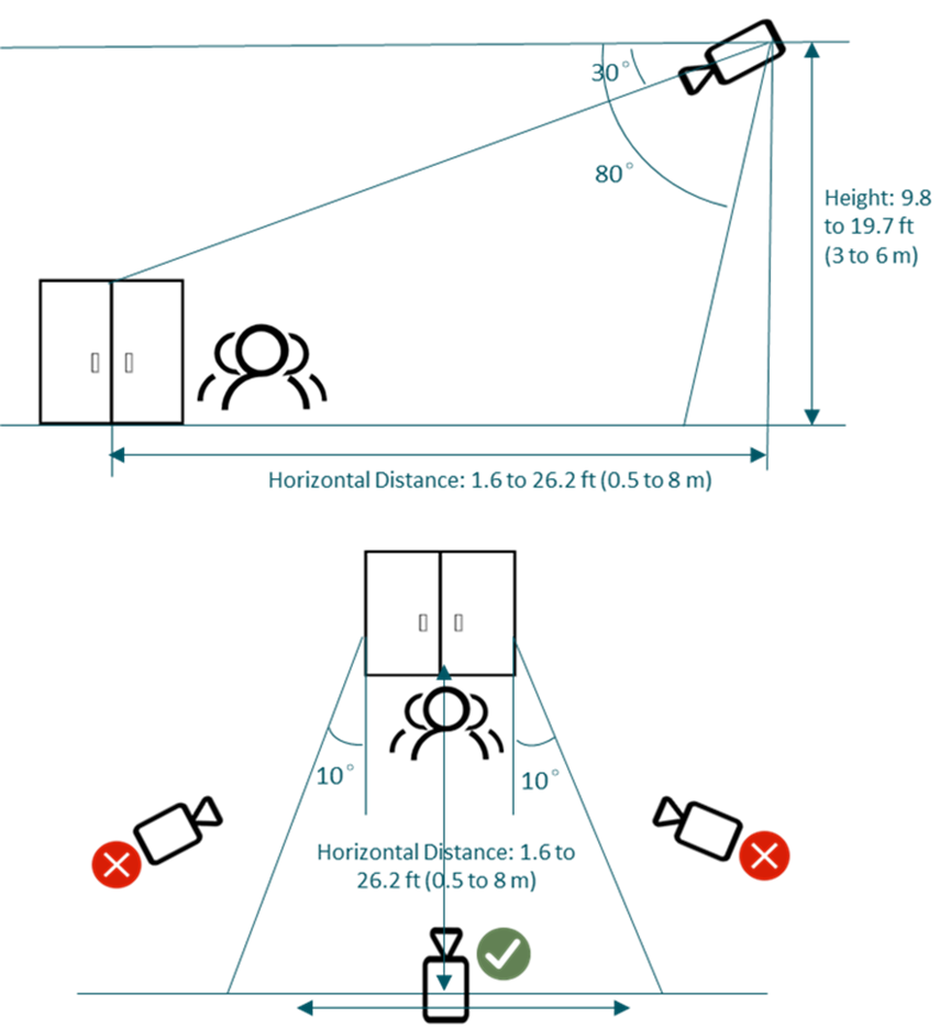
- Camera Mounting Height
The vertical distance from the camera to the ground should be between 9.8 to 19.7 ft (3 to 6 m).
- Camera Tilt Angle
The downward viewing angle between the camera’s line of sight and the horizontal plane should be set within 30°to 80°.
- Camera Placement
It is recommended to install the camera facing directly toward the entrance or exit. Avoid positioning the camera at an oblique angle to the target area.
- Installation Coordination
The height, tilt angle, and positioning of the camera must work in coordination to minimize head occlusion between individuals in the frame. Improper setup may result in missed or incorrect counts.
Recommended Deployment Conditions
- Install in Open and Clearly Defined Areas
Recommended for entrances, corridors, or open spaces with clear boundaries and a well-defined pedestrian flow direction.
- Ensure Proper Lighting Conditions
Avoid environments with insufficient lighting, backlighting, strong glare, or overexposure. For optimal detection accuracy, use during daytime or in well-lit areas — usage under night-time infrared (IR) mode is strongly discouraged.
- Avoid Clutter and Shadows in the Detection Area
Try to avoid scenes with excessive clutter, overlapping objects, or distracting shadows that may interfere with detection.
- Keep Detection Zone Free from Obstructions
Do not place the camera where items may block or partially obstruct pedestrians within the detection area
People Counting areas Configuration Requirements
- Determine People Traffic Direction
Identify the direction of customer flow — entering or exiting — based on the on-site layout.
- Define the Detection Zone and Counting Rules
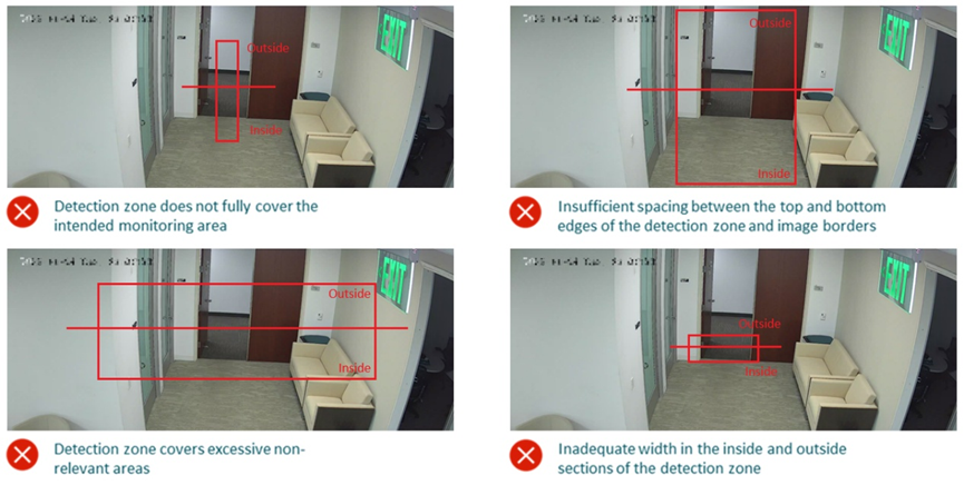
Draw the detection area and configure the entry/exit rules accordingly. Ensure the detection box fully covers the target area of interest, including both inside and outside regions.
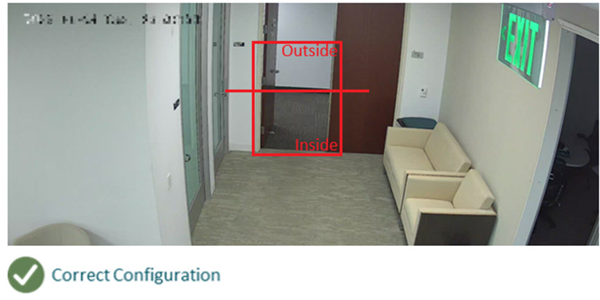
- Vertical Margins
Leave a gap between the top/bottom of the detection zone and the edges of the camera view. It is recommended to reserve at least the space of one human head (approximately 0.5 m / 1.6 ft).
- Vertical Coverage
Ensure sufficient space on both the indoor and outdoor sides heights the detection area. A minimum of four human-head widths should be reserved on each side to ensure smooth counting.
- Zone Optimization
The detection area should be properly sized — avoid making it too large or including irrelevant regions. Oversized zones may introduce uncontrolled variables that negatively affect detection accuracy.
Conclusion
People Counting is now fully enabled. This guide has outlined the requirements, configuration steps, and practical considerations to ensure proper setup. With the feature active, administrators can monitor entry and exit trends, generate accurate reports, and apply the data to real-world scenarios such as retail analysis, visitor management, and facility planning.
QA
Q1. What is the People Counting feature?
A1. People Counting is an analytics function that works with supported VIGI cameras and NVRs. It detects and counts the number of people entering or exiting a defined area or zone.
Q2. Which devices support People Counting?
A2. Selected VIGI cameras and NVRs that provide AI-based analytics are required. VIGI VMS integrates with these devices to display statistics. A list of supported devices can be found here: https://www.vigi.com/en/vigi-people-counting/product-list/.
Q3. How many people counting zones can be created?
A3. Up to three counting zones can be created per supported camera.
Q4. Where do I view the People Counting statistics?
A4. Statistics can be viewed on the VIGI VMS dashboard under People Counting and can be filtered by device, site, or time period.
Q5. Do I need a TP-Link ID to use People Counting?
A5. No, you can access People Counting through VIGI VMS - through a local controller. A TP-Link ID is needed for cloud functionality.
Q6. What are some application scenarios for People Counting?
A6. Typical uses include monitoring customer flow in retail stores, tracking visitor numbers in offices, and analyzing building entry/exit traffic.
Q7. I have received the error: “The channel is not supported.” What should I do?
A7. This error indicates that no camera supporting People Counting is currently mapped to an active NVR channel.Log in directly to the NVR web interface using its IP address and confirm that the camera is properly added to a channel. If it is not added, assign the camera to an available channel.After the camera is successfully bound to a channel, verify in VIGI VMS under Device Management that a channel number is displayed for the camera. Once the channel association is established, the error message should no longer appear.
Q8. Some options are missing located differently in VIGI Cloud VMS. Why?
A8. Support for People Counting in VIGI Cloud VMS has not yet been released. This feature will be included in a future update.
這篇faq是否有用?
您的反饋將幫助我們改善網站

